ChevyParts
My Garage
My Account
Cart
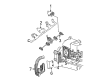
OEM Chevrolet Avalanche 1500 Fuel Rail
Engine Fuel Rail- Select Vehicle by Model
- Select Vehicle by VIN
Select Vehicle by Model
orMake
Model
Year
Select Vehicle by VIN
For the most accurate results, select vehicle by your VIN (Vehicle Identification Number).
8 Fuel Rails found


Chevrolet Avalanche 1500 Fuel Rail Part Number: 97361352
$351.85 MSRP: $714.61You Save: $362.76 (51%)

Chevrolet Avalanche 1500 Fuel Rail Part Number: 97361353
$336.68 MSRP: $683.83You Save: $347.15 (51%)


Chevrolet Avalanche 1500 Fuel Rail Part Number: 17113695
$104.95 MSRP: $327.45You Save: $222.50 (68%)Ships in 1-2 Business Days


Chevrolet Avalanche 1500 Fuel Rail Part Number: 12602113
$114.68 MSRP: $232.93You Save: $118.25 (51%)Ships in 1-2 Business Days

Chevrolet Avalanche 1500 Fuel Rail Part Number: 97303659


Chevrolet Avalanche 1500 Fuel Rail Part Number: 97208075


Chevrolet Avalanche 1500 Fuel Rail Part Number: 17113696

Chevrolet Avalanche 1500 Fuel Rail Part Number: 97303658
Chevrolet Avalanche 1500 Fuel Rail
Want to cut long-term maintenance and repair costs? Choose OEM Fuel Rail. Those parts deliver top durability you can trust. On our site, you'll find a huge catalog of genuine Chevrolet Avalanche 1500 parts. Prices are unbeatable, so you can keep more in your pocket. Every OEM Chevrolet Avalanche 1500 Fuel Rail includes a manufacturer's warranty. You can also get an easy return policy that keeps buying risk free. Fast delivery, get your car on the road quickly. It's simple to search, compare, and order. Stop guessing about quality or fit. Order today and save with parts that last.
Chevrolet Avalanche 1500 Fuel Rail Parts and Q&A
- Q: How to replace the fuel rail assembly on 4.8L, 5.3L, and 6.0L engines on Chevrolet Avalanche 1500?A:Before starting Fuel Rail assembly replacement on engines with 4.8l, 5.3l and 6.0l the fuel system pressure must be released. Start by removing the wire harness bracket nut and then detach both the evaporative emission (EVAP) purge solenoid electrical connector and generator electrical connector. The replacement process begins by cutting the stormwater from the maniflood absolute pressure sensor and Knock Sensor alongside disconnecting the Knock Sensor harness connector on the Intake Manifold and connector position assurance lock. The primary engine operation connects must be separated along with fuel injector wires on both sides. Additionally, all Fuel Rail harness clips need removal. Place the engine wire harness aside first while marking fuel injector connectors for reinstallation. Then use the cpa retainer to disconnect each fuel injector electrical connector by pulling up the retainer then pushing the tab to separate the connector. The maintenance process begins by extracting the pcv hose and detaching both fuel supply and return tubing from the Fuel Rail and afterward removing the vacuum hose of the fuel pressure regulator. Separate the Fuel Rail bolts before gently removing the Fuel Rail to prevent terminal and tip harm on injector electrical connectors. Use caps to seal off fittings and seal the holes while protecting against contaminants. A spray-based engine cleaner is acceptable for brushing the Fuel Rail yet submersion should be avoided. To examine the fuel injectors remove their lower o-ring seals from each injector and then discard them. New fuel injector lower o-ring seals require engine oil lubrication before their installation onto each injector. Apply gm p/n 12345382 threadlock to Fuel Rail bolts at their threads before installing the bolts which should be tightened to 10 n.m (89 lb in) torque. The fuel pressure regulator vacuum hose and fuel feed and return pipes and pcv hose require reattachment during this step. Secure the fuel injector electrical connectors properly while checking the correct sequence and place the engine wire harness in its position. Reconnect the main coil then the fuel injectors before installing the harness clips to the Fuel Rail while holding cpa retainers. After reattaching the MAP Sensor connect the Knock Sensor and next install the Knock Sensor harness connector onto the Intake Manifold while also connecting the evap purge solenoid electrical connector with the generator electrical connector. The last installation task includes installing the wire harness bracket nut while tightening it to 5 n.m (44 lb in), followed by fuel fill cap tightening and negative Battery Cable reconnection and a leak inspection through a sequence of turning on the ignition with engine off for 2 seconds, then turning off for 10 seconds before another ignition on check for fuel leaks.

Related Chevrolet Avalanche 1500 Parts
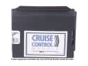 Chevrolet Avalanche 1500 Cruise Control Module
 Chevrolet Avalanche 1500 Fuel Filler Hose
 Chevrolet Avalanche 1500 Fuel Injection Pump
 Chevrolet Avalanche 1500 Fuel Injector
 Chevrolet Avalanche 1500 Fuel Injector O-Ring
 Chevrolet Avalanche 1500 Fuel Pressure Regulator
 Chevrolet Avalanche 1500 Gas Cap
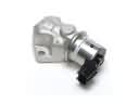 Chevrolet Avalanche 1500 Idle Control Valve
 Chevrolet Avalanche 1500 Throttle Body
 Chevrolet Avalanche 1500 Throttle Cable
 Chevrolet Avalanche 1500 Turbocharger
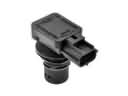 Chevrolet Avalanche 1500 Vapor Pressure Sensor