ChevyParts
My Garage
My Account
Cart
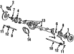
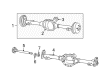
OEM Chevrolet Blazer Axle Shaft
Car Axle Shaft- Select Vehicle by Model
- Select Vehicle by VIN
Select Vehicle by Model
orMake
Model
Year
Select Vehicle by VIN
For the most accurate results, select vehicle by your VIN (Vehicle Identification Number).
72 Axle Shafts found


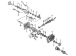
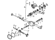
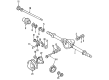
Chevrolet Blazer Pinion Shaft, Front Passenger Side Part Number: 19121909
$144.68 MSRP: $353.04You Save: $208.36 (60%)Ships in 1-2 Business Days
Chevrolet Blazer Axle Shaft, Front Part Number: 7849332
$49.28 MSRP: $88.00You Save: $38.72 (44%)Ships in 1-3 Business DaysChevrolet Blazer Axle Shaft, Front Part Number: 7849300
$51.92 MSRP: $92.72You Save: $40.80 (44%)Ships in 1-3 Business Days
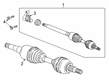
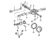
Chevrolet Blazer Axle Assembly, Front Passenger Side Part Number: 84878163
$275.61 MSRP: $473.37You Save: $197.76 (42%)Ships in 1-2 Business Days
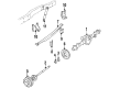
Chevrolet Blazer Axle Shafts, Rear Part Number: 85150636
$103.97 MSRP: $253.67You Save: $149.70 (60%)Ships in 1-3 Business Days
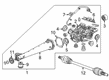
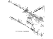
Chevrolet Blazer Tube Part Number: 84703734
$298.76 MSRP: $470.09You Save: $171.33 (37%)Ships in 1-2 Business Days


Chevrolet Blazer Output Shaft, Front Driver Side Part Number: 26006824


Chevrolet Blazer Axle Shaft, Rear Part Number: 26050549

Chevrolet Blazer Axle Shafts, Rear Part Number: 12380993
Chevrolet Blazer Axle Shaft, Rear Part Number: 26027706
Chevrolet Blazer Axle Shaft, Rear Part Number: 26033365

Chevrolet Blazer Axle Shafts Part Number: 7844114

Chevrolet Blazer Axle Shaft Part Number: 14071750
Chevrolet Blazer Axle Shaft, Driver Side Part Number: 26015323

Chevrolet Blazer Axle Shaft, Front Part Number: 15521884

Chevrolet Blazer Stub Shaft, Front Part Number: 26034184
Chevrolet Blazer Axle Shaft, Inner Passenger Side Part Number: 458878
Chevrolet Blazer Axle Shaft, Rear Part Number: 26033364
Chevrolet Blazer Axle Shafts, Rear Part Number: 26058925
| Page 1 of 4 |Next >
1-20 of 72 Results
Chevrolet Blazer Axle Shaft
Want to cut long-term maintenance and repair costs? Choose OEM Axle Shaft. Those parts deliver top durability you can trust. On our site, you'll find a huge catalog of genuine Chevrolet Blazer parts. Prices are unbeatable, so you can keep more in your pocket. Every OEM Chevrolet Blazer Axle Shaft includes a manufacturer's warranty. You can also get an easy return policy that keeps buying risk free. Fast delivery, get your car on the road quickly. It's simple to search, compare, and order. Stop guessing about quality or fit. Order today and save with parts that last.
Chevrolet Blazer Axle Shaft is one of the model's critical components; it transfers torque to the wheels to enable individual rotation to improve grip. To clarify, these steel shafts transmit power generated from the differential to the individual wheels as they bear vehicle weight as well as transmit driving torque and help in keeping wheels in proper alignment. Blazer axle shafts may be of different kinds depending on functionality- the live axle shaft for torque transfer and the non-driving axle shaft for suspension and the steering mechanism. Some of these include the straight axle for use with the heavy trucks, split axle for the modern day cars, and the drive axles with the differentials are very essential in the use of the front and rear wheel drive systems. Besides, primary visual inspections should be done periodically since the deteriorated component and lack of lubrication may result in failure in the long run.
Chevrolet Blazer Axle Shaft Parts and Q&A
- Q: How to replace the wheel axle shaft on Chevrolet Blazer?A:The Axle Shaft replacement process begins with Steering Column unlocking to free up the steering linkage and adds vehicle elevation and safety stands for support. To prevent drive axle rotation, put a drift tool through the brake caliper that penetrates one rotor vane while removing the two front tire and wheel assemblies. The brake caliper support with wire must be prepared before uninstalling the axle nut and washer followed by brake rotor drift removal and front brake rotors extraction. Before proceeding remove the brackets which secure the abs wire and brake hose to the upper Control Arm thus also the abs bracket which sits above the upper Control Arm Ball Joint. Secure the frame on the hoist while preventing any damage to components by the safety stand. Install one safety stand underneath the lower Control Arm then position a second safety stand to stabilize the Steering Knuckle assembly together with lower Control Arm. The Axle Shaft separation from the hub requires a sharp hammer strike onto the axle outer end while using a brass drift. First support the Steering Knuckle with wire to avoid damage before breaking the upper Ball Joint from the Steering Knuckle then removing the bottom of the shock absorber to disconnect the lower Ball Joint from the Steering Knuckle. The Axle Shaft movement toward the differential carrier after loosening the lower Ball Joint creates enough space for removing the knuckle assembly before towing out the axle. Lower down the safety stand from the lower Control Arm because it lowers torsion bar pressure but maintain attention to avoid damaging the axle seal when removing the differential carrier shield. After unscrewing the front differential carrier shield users should strike a block of wood or brass drift against the tripot housing to disengage the snap ring pressure from axle shafts before extraction. Pull the axle directly from the differential carrier using support to prevent boot damages. The Axle Shaft(s) must remain in place as the vehicle should not support weight on the front wheels and should not operate without both Axle Shaft(s) and Axle Shaft nut(s) installed. Finally, remove the drive axle. Protect boot material by using a shop towel to cover the shock mounting bracket and ball stud of the lower Control Arm and all points with edges during installation. Put the shaft into the differential carrier through the following steps: position the splines on the shaft with the differential carrier while inserting the drive axle into the differential carrier seal and continue pushing straight until the snap ring reaches its seat. When the lower Control Arm sits on the safety stand you can start guiding the lower ball stud into position on the Steering Knuckle while partially installing the drive axle. Install the lower Ball Joint to the Steering Knuckle before putting on the lower shock absorber part followed by attaching the upper Ball Joint and drive axle washer with its nut tightened to 140 nm (103 ft. Lbs.). The abs bracket positions above the upper Control Arm Ball Joint before adding brackets that hold the abs wire and brake hose from the upper Control Arm followed by front brake rotor installation. The front differential carrier shield needs installation followed by removing the frame strap and installing both front tire and wheel assemblies before lowering the vehicle.

Related Chevrolet Blazer Parts
 Chevrolet Blazer CV Joint
 Chevrolet Blazer Sway Bar Link
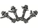 Chevrolet Blazer Alignment Bolt
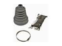 Chevrolet Blazer CV Boot
 Chevrolet Blazer Coil Springs
 Chevrolet Blazer Control Arm
 Chevrolet Blazer Control Arm Bolt
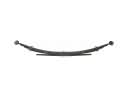 Chevrolet Blazer Leaf Spring
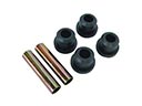 Chevrolet Blazer Leaf Spring Bushing
 Chevrolet Blazer Sway Bar Bushing
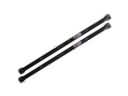 Chevrolet Blazer Torsion Bar
 Chevrolet Blazer Wheel Cover