ChevyParts
My Garage
My Account
Cart
OEM GMC Savana 1500 Brake Dust Shields
Brake Backing Plate- Select Vehicle by Model
- Select Vehicle by VIN
Select Vehicle by Model
orMake
Model
Year
Select Vehicle by VIN
For the most accurate results, select vehicle by your VIN (Vehicle Identification Number).
7 Brake Dust Shields found


GMC Savana 1500 Backing Plate, Rear Part Number: 19178785
$16.94 MSRP: $51.43You Save: $34.49 (68%)


GMC Savana 1500 Splash Shield, Passenger Side Part Number: 19211698

GMC Savana 1500 Splash Shield, Driver Side Part Number: 19211697


GMC Savana 1500 Backing Plate Part Number: 15650129
GMC Savana 1500 Backing Plate, Front Driver Side Part Number: 25918337
GMC Savana 1500 Backing Plate Part Number: 15650130
GMC Savana 1500 Brake Dust Shields
Want to cut long-term maintenance and repair costs? Choose OEM Brake Dust Shields. Those parts deliver top durability you can trust. On our site, you'll find a huge catalog of genuine GMC Savana 1500 parts. Prices are unbeatable, so you can keep more in your pocket. Every OEM GMC Savana 1500 Brake Dust Shields includes a manufacturer's warranty. You can also get an easy return policy that keeps buying risk free. Fast delivery, get your car on the road quickly. It's simple to search, compare, and order. Stop guessing about quality or fit. Order today and save with parts that last.
GMC Savana 1500 Brake Dust Shields Parts Questions & Experts Answers
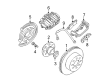
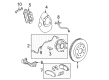
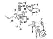
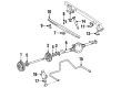
- Q: How to replace the brake dust shields on GMC Savana 1500?A:To service the disc Brake Dust Shields first put the vehicle on stands and then remove the tire wheel assembly brake caliper hub and rotor. Separate the Wheel Speed Sensor electrical connector and take off the rosebud clip from the frame while keeping note of the sensor wire clip position at the shock tower which requires reinstalling at 45 degrees to the vehicle's center line. Disconnect bolt 9 and washer 15 holding the sensor wire clip at the shock tower and then take off rosebud clip from upper Control Arm at 7300 gvw c6a. Take out the bolt and nut which secure the sensor wire clip at the upper Ball Joint assembly (parts 5,12). The Wheel Speed Sensor stays fixed to its position on the dust shields since it needs only a nut/bolt placement at the top hole rather than removal. Take out the dust shield assembly and its face seal by first removing all dust shield bolts then the Wheel Speed Sensor and gasket. Carefully remove any dirt from both the dust shield gasket region and the knuckle. Position the dust shield gasket on the knuckle spindle first before installing the Wheel Speed Sensor and dust shield set. Secure the dust shield mounting bolts using 26 nm torque which is equivalent to 19 ft. Lbs. Place the sensor wire clip back on top of Ball Joint (5,12), then tighten both wheel sensor wire clip nut (4,11) and bolt (7,14) to 17 nm (13 ft. Lbs). Only for the 7300 lb. Gvw (C6A) models install the wire clip to the upper Control Arm. Made to meet the shock tower sensor wire clip at a 45-degree orientation to the car's center axis and fasten it with the bolt at the shock tower while tightening to 15 nm (11 ft. Lbs.). Connect the Wheel Speed Sensor connector to the inner frame rail and attach its rosebud clip before joining it to the vehicle harness. Put back all hardware elements before testing the vehicle beyond 32 km/h (20 mph) speed. Use special monitoring equipment to erase diagnostic problems and to check wheel movement accuracy during testing.

Related GMC Savana 1500 Parts
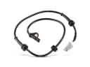 GMC Savana 1500 ABS Sensor
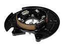 GMC Savana 1500 Brake Backing Plate
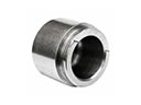 GMC Savana 1500 Brake Caliper Piston
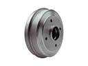 GMC Savana 1500 Brake Drum
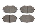 GMC Savana 1500 Brake Pad
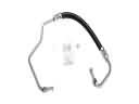 GMC Savana 1500 Hydraulic Hose
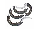 GMC Savana 1500 Parking Brake Shoe
 GMC Savana 1500 Spindle Nut
 GMC Savana 1500 Wheel Bearing
 GMC Savana 1500 Wheel Hub
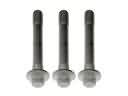 GMC Savana 1500 Wheel Hub Bolt
 GMC Savana 1500 Wheel Speed Sensor